During the past months, we have been working on improving the absolute accuracy of our robot collection. As a result, we successfully improved the accuracy of our smart manufacturing robots to the 0,1 mm range. Check out the video to see how iterated towards these improvements, and read on to learn more!
Step 1: small scale testing on cobot
The very first step towards achieving extreme accuracy on our XL robots was to start small: we had to learn how the process of recording a robot’s accuracy is defined, and practice the procedure. Therefore, we conducted a series of small scale test runs on our cobot and, as a bonus, gained more insight on its path accuracy too.
In order to define our initial test setup, we referred to ISO9283 – “Manipulating industrial robots – Performance criteria and related test methods”. This standard includes a procedure to calculate the path accuracy of a robot, which is the deviation between the path the robot has been programmed to follow and the one it actually takes when moving from A to B. The procedure is based on performing linear motions within a predefined cube in the robot’s working area. We programmed our cobot to follow this procedure for these initial small-scale tests.
Given that we had only just received our Leica laser tracker, we still had to learn how to use that system as well. With assistance from K-LOOPS, we were able to understand how to use the laser tracker to set up the reference frames of the robot with utmost precision. This ensured any subsequent measurements of the cobot by the laser tracker could accurately be compared with the robot’s programmed position.
Step 2: medium scale testing on Kuka robot
Up next was the work on our Kuka robot. This was a step up in complexity on a number of fronts. First of all, the Kuka robot is much larger and it has an additional degree of freedom due to being mounted on tracks (see video). Moreover, our ambition for the Kuka robot was no longer to use the external laser tracker merely for measuring the path accuracy of the robot. Now we also aimed to correct its positioning in real time. Both when stationary and while making moves. Demonstrating this feature was part of our efforts for the PeneloPe project.
We use this Kuka robot at SAM XL for Automated Fibre Placement (see this post) and 3D-printing of large structures. Additionally, we plan to use it for milling purposes in the future as well. The quality and consistency of these manufacturing processes is directly impacted by the positioning accuracy of the end-effector. Thus, any accuracy improvements we achieve can be directly translated to an improvement of our capabilities in these areas. Especially for milling operations, the live feedback control system really comes into its own, because it can correct the deflections that result from the reaction forces being exerted on the milling end-effector.
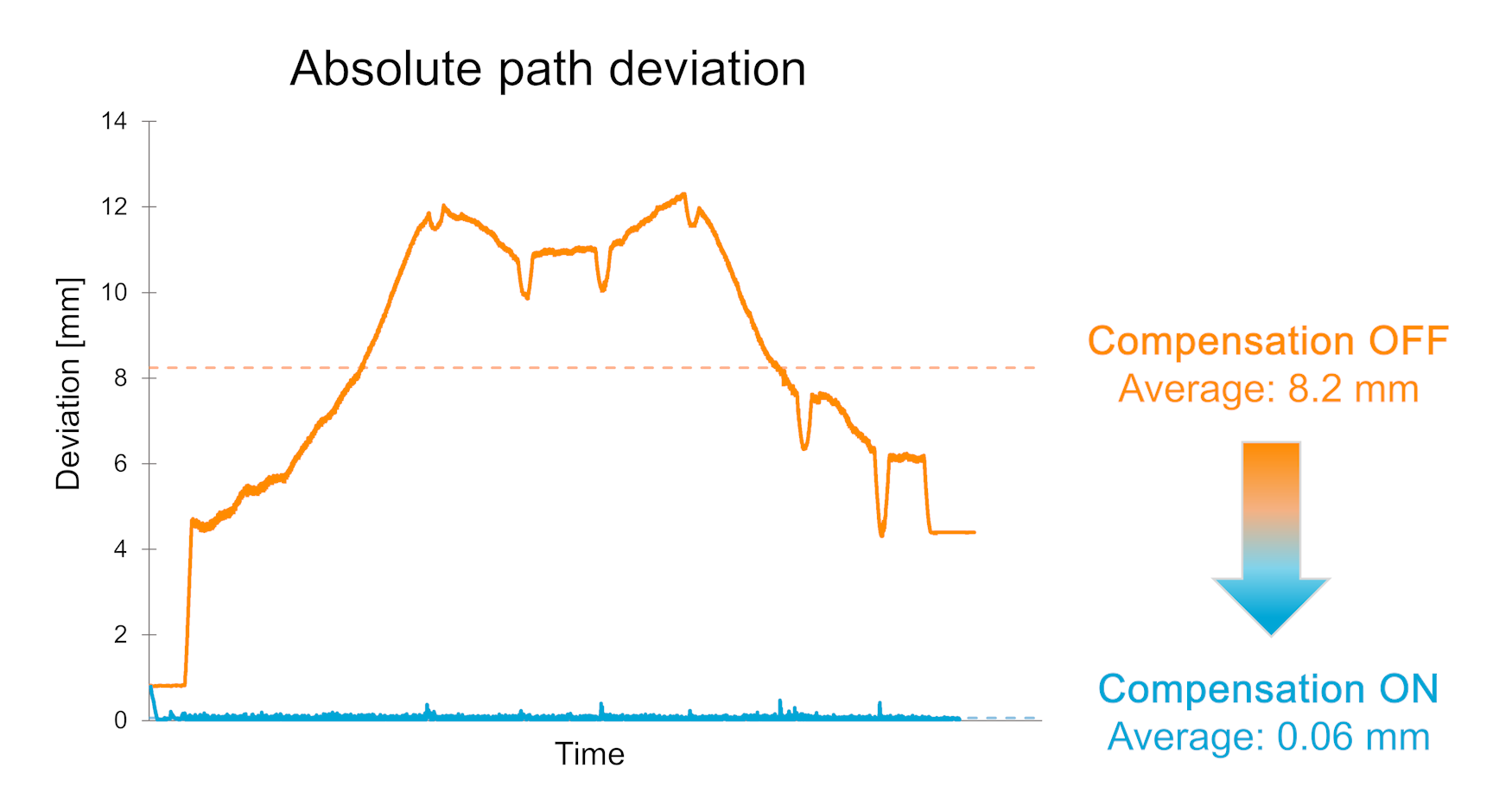
The graph below shows the substantial improvement that the live feedback control system provides. While performing the ‘XL’ motion displayed in the video, the absolute path deviation dropped from an average of 8.2 mm to just 0.06 mm: a 137x improvement! All this was made possible by K-LOOPS’ novel software, and we at SAM XL were glad to be their first technology partner to implement this. Meanwhile, K-LOOPS showcased that their technology also functions on track-mounted robots. A fruitful collaboration.
Step 3: scaling up to XL Gantry robot
The third and final part of the accuracy improvement project was to scale up the technology and know-how to our Gantry robot. As with the Kuka robot, improving the accuracy of this XL machine will improve the quality of the manufacturing processes carried out with it. This is particularly relevant for the continuous ultrasonic welding end-effector that we aim to install on this robot in the future. Our goal is to make top quality continuous ultrasonic welds of several meters in length.
The size of the Gantry robot inherently comes with accuracy challenges, which is shown clearly in the video. At first, the robot wasn’t even capable of keeping a marker pressed against a whiteboard. As explained by one of our Gantry engineers: “The cause of the inaccuracies we experience with the Gantry robot are non-linearities related to the sheer size and weight of this massive robot.”
Our engineers determined that the best approach to solve this issue would be to calibrate the Gantry robot. This calibration was performed with the laser tracker and the help of a team from Isios who provided expertise on the Gantry’s control system. The calibration succesfully improved the accuracy, reducing the mean error from 2.29 mm to 0.34 mm. The table below illustrates the significant improvements. Thank you Isios for helping to make this possible!
